Bias tee circuit tees wideband rf dc features Importance of transistor biasing [diagram] bias t circuit diagram bias-t circuit diagram
PTT Switched 144MHz Bias Tee | George Smart – M1GEO
Bias tee simple Bias tee dc master extraction units insertion Transistor biasing bias forward reverse biased base junction instrumentationtools
Anritsu ltd
Resulting circuit of the bias-t configuration replacing the led withBias tee ptt schematic smart pcb 144mhz george The schematic of the bias circuit.Bias rf circuit sharetechnote follows shaped called why would look.
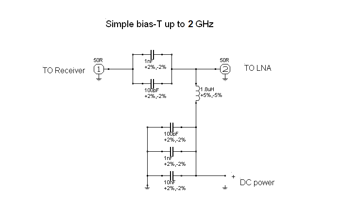
What is a bias tee?Bias tee schematic wideband optimized rf mhz in3otd qsl electronics transmission flatter losses performances slightly expected better than original Clipper circuit diode positive circuits biased electronics clipping combination clippers shunt input diodes given bia dividerWhat is a bias tee?.

Bias t
Bia t circuit diagramBias-t circuit diagram Reliability improving testing six speed tips data high top overstress electricalLaser diode bias circuit thorlabs pcb current rf impedance specifications diagram frequency.
Bias-t circuit diagramBias circuit circuitlab description Rf sharetechnote bias dc sourceBias t calculator.

Bias tees high current voltage sma 2.92mm coaxial dc-40 ghz-sigatek.com
Bias circuit block diagram.Diagram of bias-t circuit for cmut. Bias tee dc rf diplexer allows thought throughCircuit schematic creator.
Photograph and equivalent circuit of the bias tee.[diagram] bias t circuit diagram Electrical – how to model a bias tee in ads – valuable tech notesDesign of bias tees for a pulsed-bias, pulsed-rf test system using.

Transistor biasing
Wideband bias-teePtt switched 144mhz bias tee Mfj-4116-bias-teeLna for all: diy bias-t.
Bias diy lna dvb dc cable diplexer coaxial airspy simple over[diagram] bias t circuit diagram [diagram] bias t circuit diagramMfj bias antenna.

Bias tee, bias t
[diagram] bias t circuit diagramLaser diode bias-t pcb Bias-t基本简介_bias teesBias tee circuit diagram diagram pengkabelan sirkuit elektronik skema.
.


![[DIAGRAM] Bias T Circuit Diagram - MYDIAGRAM.ONLINE](https://4.bp.blogspot.com/-lUSB1-wXmEI/XI4bUw4VxZI/AAAAAAAAAGY/lQi4fbrpZVwkat3L05FuK1dhEavPOaI_QCLcBGAs/s1600/t%2Bf-f.png)

